Carbon fibres reinforced with Carbon Nanotubes
Référence
86312-01 / 02371-01 / 04669-01 / 04677-01
Mots-clés
Hybrid reinforcement, Composite material, CVD, Carbon nanotube, Carbon fiber, Microparticles
Inventeurs
JinBo BAI
Statut commercial
Exclusive or non-exclusive licenses, Collaborative agreement
Laboratoire
Laboratoire de Mécaniques des Sols, Structures et Matériaux, a CNRS laboratory (UMR 8579), France.
Description
CONTEXT
Composite materials belong to our every day life from window frame to aiplane parts. It is well known that the propertes of compistes depend simultaneously on that of the marix and the filler respectively and on the aspect ratio of the fillers. Fillers can generaly enhance mechanical properties of the composites but may also bring new propoerties like electrical or thermal conductivity, flame our UV or chemical …
Nanofillers and especially carbon ones have encountered a large interest due to their inherent properties.
The team proposes here a new concept of composite taking advantage of both types to get a synergetic effect between traditionnal microfillers and CNT grown on their surface and enhance mechanical and functional characteristics (thermal or electrical conductivity). Two sorts of mechanisms are acting simultaneously: at the nanoscale local physico-chemical reactions are activated, macromolecular movements, dislocation and microcrack are modified while at the microscale cracks propagation and cavitation are inhibited.
TECHNICAL DESCRIPTION
This patented process is based on chemical vapor deposition (CVD) of CNT on conventionnal microfillers/ reinforcement material which may be:
- long or short fibres : carbon, glass, alumina, silicon carbide (SiC), ;
- ceramic materials chosen like particles, whiskers, fibrills of silicon nitride (Si3N4), boron carbide (B4C), silicon carbide (SiC), tintanium carbide (TiC), cordierite (Al3Mg2AlSi5O18), mullite (Al6Si2O13), nitrure d’aluminium (AlN), boron nitride (NB), alumina (Al2O3), borure d’aluminium (AlB2), magnesium oxide (MgO), zinc oxide (ZnO), magnetic iron oxide (Fe3O4) zirconia (Zr2O), silica (Si2O), silica fumes, CaO, La2CuO4, La2NiO4, La2SrCuO4, Nd2CuO4, TiO2, Y2O3, alumina silicates (clays).
- metallic wires (Fe, Ni, Co…)
a) coating of particles/ short fibers
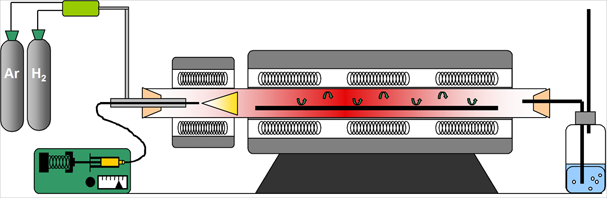
The filler to be coated is placed on a quartz plate in the CVD oven under inert gas and heated up to 350-850°C regarding its nature and the desired final product. Then the cabon precursor (acetylen/xylene) is injected with the ferrocene catalyst for a few minutes and the system is allowed to cool down.
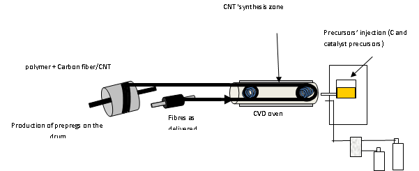
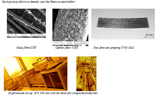
The experimental set up is presented bellow; as-received fibers are drawn through pulleys in the oven (D 100mm) where CNTs are grown and then are wound on the drum. For continuous fibers it is necessary to adapt the residence time in the oven so a winding ceramic system has been implemented in the oven (up to length = 8 m simultaneously ). The drum may be covered by a polymer sheet (epoxy prepreg) which is cut and flattened at the end of the experiment to get a « prepreg » of dimensions 720 mm x 250 mm.
It is also possible to coat the fiber wih a carbon nanolayer (graphitization) to fix the CNTs on the fibres and improve electrical and thermal conductivity. Other solutions have been proposed like plasma treatment (atmospheric or low pressure), dipping in a polymer bath but as the polymer is non conducting, one lose the advantage of CNTs.
c) Common parameters
The various CVD parameters (Synthesis temperature, gas ratios and gas and liquid flows) are easily adjusted to control the CNTs :length and diameter of CNT (3 – 20 nm uniform and monomodal, Diameter can be increased step by step up to 200nm without changing either the inner diameter nor the length) ; Density of CNT on the filler and Homogeneity of CNT on the filler (uniform distribution or local CNTs’ packs..).
BENEFITS
The process is easy to set up and all CNTs’ characteristics can be finely tuned by controlling the process parameters. The last step of coating the hybrid CNT-filler improve the adhesion of CNT on the filler and enhance the composite properties. The hybrid nano/micro fillers(CNT grown on the micro particles/short fibers or micro long fibers) showed advantages compared to the traditional micro or nano fillers alone. The concept reduces largely the risk of CNT release during the CVD, filler adding and composite preparation steps. Greatly reduced quantity was used to achieve equivalent or even much higher performance of composites.
INDUSTRIAL APPLICATIONS
The innovation can be used in all applications in which improved mechanicals (structural composites) or electrical properties of composites or 3D structure with high surface area or catalyst ‘s support are expected: aeronautics, battery, supercapacitors, field effect transistors,…
Particles hybrids may find applications in varnishes, paints and composites or catalyst ‘s support.
As the fillers are already known from end users there is no necessity to change the process parameters of composite production. Furthermore it has been proved that CNT can also serve as in-situ sensors (of damage, cracking, cavitation etc) in structural composites and the correlation that we have demonstrated between mechanical and electrical properties of composites allows monitoring the elastic/ plastic deformation zone change of the composite part during service life.
DEVELOPMENT STAGE
The industrialization required a larger CVD oven and control equipment but the fundamental set up has been successfully developed. CNT coating of particles and fibers has been demonstrated as well as the inherent advantages of these hybrid reinforcement materials.
The process is quick and continuous and parameters are controlled to produce the required CNT’s geometry (length, diameter). Sanitary issues have also been addressed through the further coating of hybrid fillers which may be considered as a “next step” of the complete process.
a) Particles
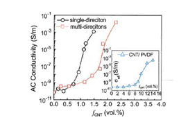
CNT have been grown on SiC Particles either in one direction Single Direction SDCNT-SiC or in Multi Direction MDCNT-SiC [i]. The following figure presents the AC conductivity for various %wt of CNT-SiC PVDF composites and compares these values to CNT PVDF composites. Both families of materials show a percolation threshold but the CNT-SiC composites display o lower value threshold and the calculated values (fitted curves) are 0,70; 1,47 and 10wt% for SDCNT-SiC ; MDCNT-SiC and CNT composites respectively. Furthermore a large dielectric permittivity of more than 8700 and 2100 at 100 Hz could be obtained at a low CNT loading of 2.30 vol% and 1.48 vol% in the MDCNT-SiCs and SDCNT-SC composites respectively which is a significant improvement as CNTs on each SiC microplate are oriented along an axis and separated by a thin polymer matrix, giving rise to a network of microcapacitors
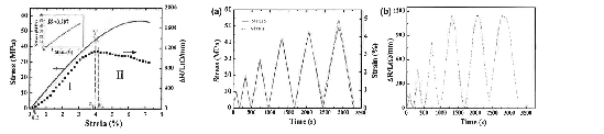
CNT have been grown on SiC Particles[i] and various (0.6-1.2wt%) epoxy composites have been produced and tensile tests performed during which the in suit electrical resistance has been measured (0.7wt%). The resistance monotonically increases and then begins to decrease when the strain passes a critical value: before this value the curve displays a typical linear elastic behavior (Hooke’s law). To check the yield point and appearance of permanent plastic deformation near said point, cyclic loading experiments have been realized (maximum stress increases with cycle number but minimum stress is always 0). As it can be seen on fig (a) a residual strain appears after the fifth cycle which corresponds on fig (b) to an irreversible resistance (in situ electrical resistance measurements).
=> Direct correlation between mechanical cracks and electrical behavior of the composite and new way to follow the composite’s health.
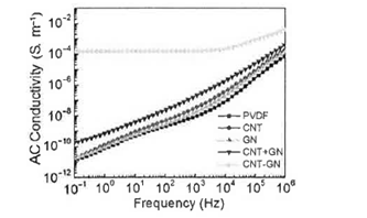
Few layered graphene (GN) were coated by the process (GN-CNT) and various composites were produced (see ref[i]): either the coated graphene GN-CNT or a mix of CNT and graphène GN+CNT with the same filler content (6.6wt%) and the same ration CNT/GN= 1,1 or CNT or GN composite (always same filler content) . The following figure represents the frequency dependence of AC conductivity of PVDF composites at room temperature. CNT and GN composites show no improvement in the conductivity. GN-CNT show a synergistic effect with an increase of 7 orders of magnitude at 0.1Hz (1.310-11 -1.6 10-4 S/m) and with a DC behavior in the frequency range from 10-1 to 104 Hz. Comparison with GN +CNT composites only display one order of magnitude improvement.
=> Hybrid fillers can be used at a lower filling % for the same electrical benefits and without changing process parameters as microfillers are used.
b) Continuous fibers
CNTs have been grown of Carbon Fibers. After the surface treatment, single fiber fragmentation test was used to assess the interfacial shear strength (IFSS) of carbon fiber/epoxy composites. Compared with the as-received CFs, the epoxy sizing and the grafting with 2 wt% CNTs of 10 nm in diameter contributed to an improvement in IFSS of up to 35% and 60%, respectively. A further heat treatment and epoxy sizing could contribute to an additional increase of 108%.
2 mm thick Composite plates were prepared for example T700/M21 with or without CNT coated on the fiber surface (CNT/fiber ratio around 2 wt%.) by our continuous CVD process. The ILSS of all composites are in the range of 100 MPa while the electrical conductivity are more or less the same in the fiber direction, around 4000 S/m; that in the traverse direction increased from 2.5 S/m to 250 S/m (T700-CNT), that in the thickness direction from 0.02 S/m to 20-100 S/m (T700-CNT).
=> Hybrid fillers dramatically increase electrical conductivity in traverse and thickness direction
[1] Carbon 51 (2013) 355-364 W. Li & al The controlled formation of hybrid structures of MW CNT on SiC plate like particle and their synergetic effect as a filler in poly(vinylidene fluoride) based composites.
[2] Carbon 50 (2012) 4291-4301 W. Li & al The use of vertically aligned CNT grown on SiC for in situ sensing of elastic and plastic deformation in electrically percolative epoxy composites
[3] Journal of Nanoscience and nanotechnology, Vol 12, 1-6, 2012, A. Dichiara & al, Chemical Vapor Deposoition Synthesis of CNT graphène nanosheet hybrids and their application in Polymer Composites
For further information, please contact us (Ref 86312-01 / 02371-01 / 04669-01 / 04677-01 / 05169-01)
Besoin de plus d'informations ?
Nous contacterTechnologies Liées
-
15.02.2017
Large size and high quality graphene on silicium
Matériaux – Revêtements, Autres technologies 04490-01
-
13.01.2016
One step in-situ graphene oxide reduction in composite
Matériaux – Revêtements 08107-01
-
07.12.2015
Packaging with two-color visual effect for decoration or identification
Matériaux – Revêtements 06693-01